



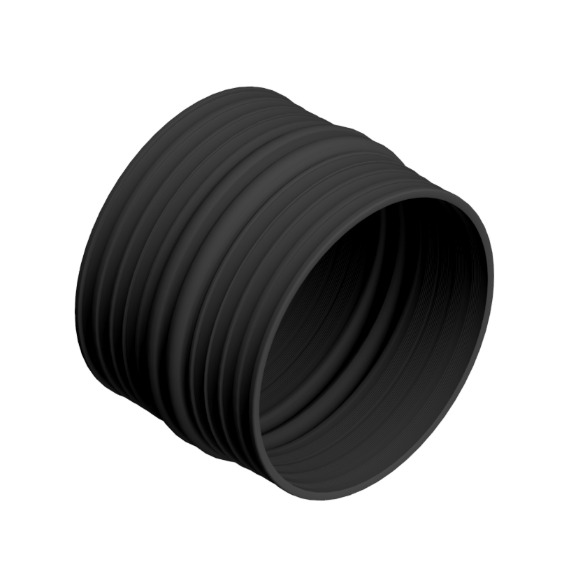
Corrugated Coupler
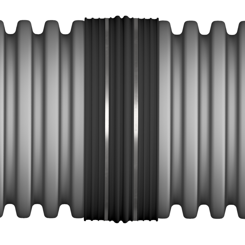
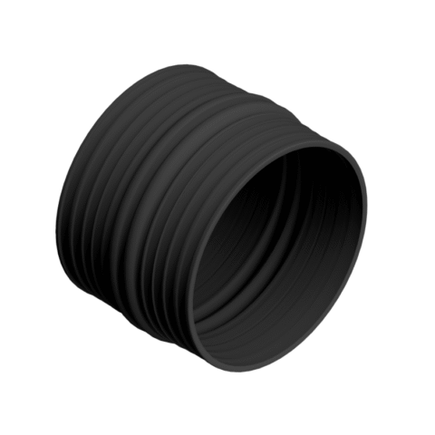
The Corrugated Coupler is designed to join corrugated HDPE, PP, and select PVC drainage pipe in demanding field conditions. It supports secure connections for repair work and protects against root invasion and potential soil disruption arising from fitting transitions and new drainage system installations.
What It Is
Engineered for dependable, pipe-to-pipe connections, the Press-Seal Corrugated Coupler helps create secure, leak-resistant joints in drainage systems with its quick installation and durable field performance.
The Corrugated Coupler is designed to join corrugated HDPE, PP, and select PVC drainage pipe in demanding field conditions. It supports secure connections for repair work and protects against root invasion and potential soil disruption arising from fitting transitions and new drainage system installations.
Standard pipe sizes between 12” and 60” (304 mm – 1524 mm). Corrugated Couplers are specific to pipe manufacturer, and pipe type. Press-Seal does not certify utilizing these couplers without regard to pipe manufacturer and pipe type.
Depending on project requirements, the Corrugated Coupler can be configured for soiltight, silt-tight, or watertight performance. The coupler and high quality clamps are packaged as separate components and are ready for immediate field installation.
Literature
Features & Benefits
- Creates a dependable connection between corrugated & PVC pipe sections and compatible fittings
- Helps improve resistance to infiltration and exfiltration in gravity-flow drainage systems
- Supports a faster installation with a field-friendly design that minimizes complexity
- Offers durable performance in buried infrastructure exposed to moisture, soil movement, and typical drainage conditions
- Accommodates a range of pipe materials and outside diameters for added installation flexibility
- Can help reduce maintenance risks by improving connection integrity over time
- Supplied with our standard corrosion-resistant 304 stainless steel quick release external bands for applications requiring repeatable connection restraints, enhanced watertight performance and long-term durability
- Type 316 stainless steel bands are also available for more demanding corrosion-resistant applications
- Common sizes of 12″–60″ (304 mm–1524 mm)
- Rubber engineered to improve quality delivery
Meets or Exceeds
- Coupler material meets and/or exceeds ASTM F477 material requirements for elastomeric sealing performance
- Watertight installations may be designed to meet ASTM D3212 when paired with
appropriate external bands or tolerance devices - Applicable drainage references may include AASHTO M294, ASTM F2306, and ASTM F2648, depending on pipe and project criteria
Applications
- Agricultural, site development, and other gravity-flow water management applications when applicable
- Storm water conveyance and municipal drainage systems
- Culvert and roadway drainage connections
- Repair and rehabilitation of existing corrugated pipe runs
- Pipe-to-fitting transitions in commercial and residential drainage installations
Sealing Option A (Preferred)
Use when pipe/corrugation size allows for multiple clamp grooves to occupy one corrugation crown at the same time.
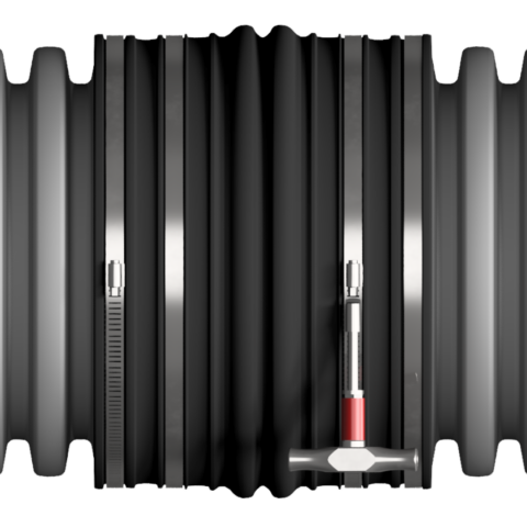
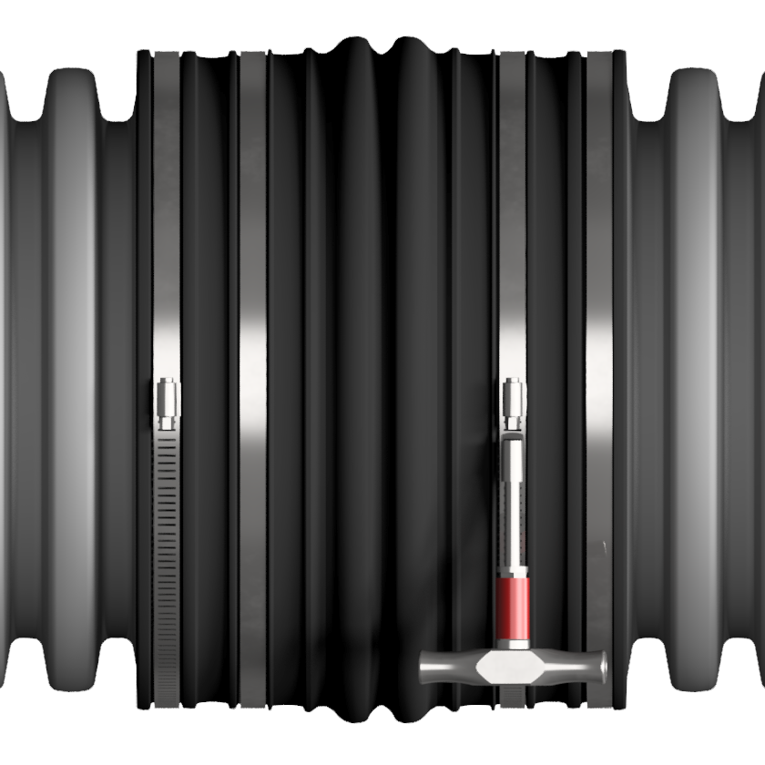
- In this installation, one set of take-up clamps is shown during the installation process. A second set of clamps may be used to provide additional sealing protection for demanding installation conditions or service requirements.
- Remove any imperfections from the corrugation crowns where the corrugated coupler is to be placed (standing ribs, parting lines, excess flash, pitting, etc.). Failure to remove these defects can create potential leak paths.
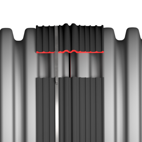
- Ensure the coupler is in the correct orientation. The clamping grooves should be facing outward, and the middle of the coupler should have two
humps showing. - Fit one end of the coupler onto the cut segments
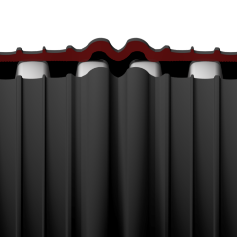
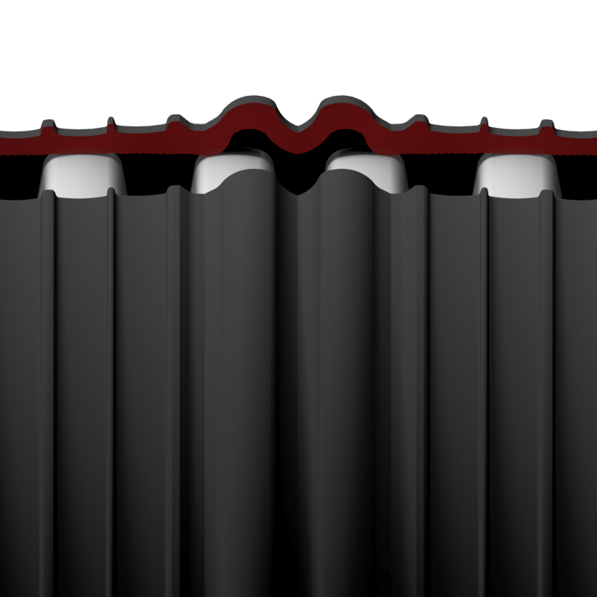
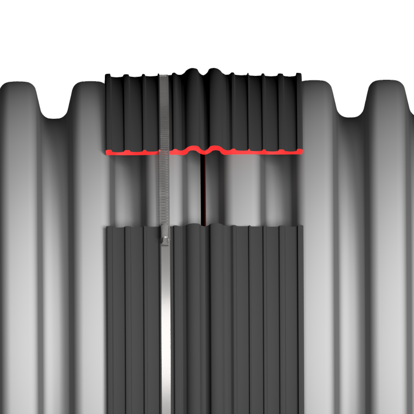
of the pipe. Keep the coupler’s edge and the next corrugation. - Adjust the position of the coupler on the pipe such that the targeted clamping grooves are directly above the corrugation crowns. Observe the fit by running your fingers over the intended grooves to verify proper fitting. A cutaway is provided here for fitting visualization and is not present on the part.
- Take the included take-up clamp(s) of corresponding size and install it/them on the targeted corrugation crowns. Use a T-Handle torque wrench to tighten the clamp to 60in-lbs. If using multiple clamps per each side of the pipe gap, install the clamps such that they are tightening in opposite directions, tightening both incrementally.
- Repeat steps 2-4 on the other segment of pipe. Ensure the fitting of the coupler is symmetric on both sides, minimizing the gap between the pipe segments while clamping onto the innermost corrugation crowns when possible.
Sealing Option B
Use when pipe/corrugation size allows one clamp groove to occupy one corrugation crown at a time.
- In this installation, two sets of take-up clamps are shown during the installation process. The additional set of clamps may be added when additional sealing performance is required.
- Remove any imperfections from the corrugation crowns where the corrugated coupler is to be placed (standing ribs, parting lines, excess flash, pitting, etc.). Failure to remove these defects can create potential leak paths.
- Ensure the coupler is in the correct orientation. The clamping grooves should be facing outward, and the middle of the coupler should have two
humps showing. - Fit one end of the coupler onto the cut segments
of the pipe. Keep the coupler’s edge and the next corrugation. - Adjust the position of the coupler on the pipe such that the targeted clamping grooves are directly above the corrugation crowns. Observe the fit by running your fingers over the intended grooves to verify proper fitting. A cutaway is provided here for fitting visualization and is not present on the part.
- Adjust the position of the coupler on the pipe such that the targeted clamping grooves are directly above the corrugation crowns. Observe the fit by running your fingers over the intended grooves to verify proper fitting. A cutaway is provided here for fitting visualization and is not present on the part.
- Repeat steps 2-4 on the other segment of pipe. Ensure the fitting of the coupler is symmetric on both sides, minimizing the gap between the pipe segments while clamping onto the innermost corrugation crowns when possible.