
HDPE Waterstop Gaskets
HDPE Waterstop is a rubber ring which is compressed around the pipe circumference using stainless steel clamps, preventing infiltration and exfiltration between the HDPE Waterstop and the pipe. It is then either grouted into an existing structure, or has a new structure poured around it.
What It Is
HDPE Waterstop is a rubber ring which is compressed around the pipe circumference using stainless steel clamps, preventing infiltration and exfiltration between the HDPE Waterstop and the pipe. It is then either grouted into an existing structure, or has a new structure poured around it.
Literature
Full Literature
How It Works
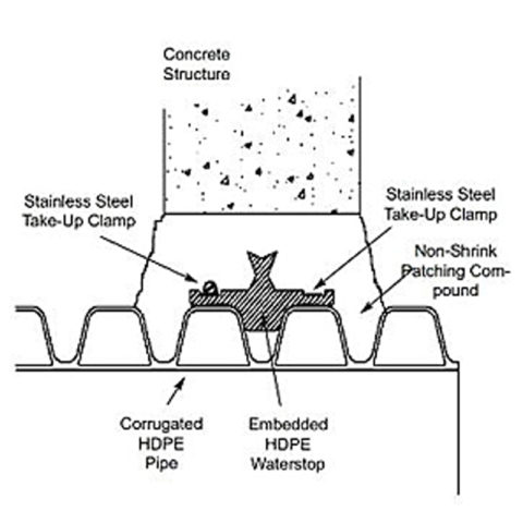
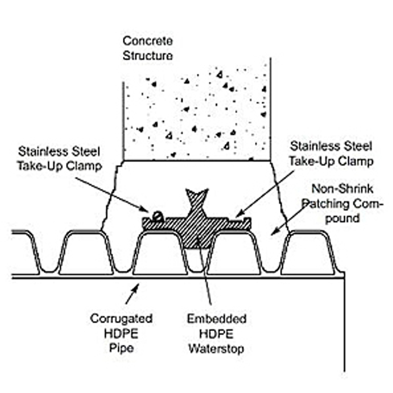
- Stainless steel clamps secure the connector to the pipe.
- The connector is placed to follow the arc of the manhole wall and the stainless steel clamp is placed straight across the confinement area.
- The pipe is placed in position and grouted in place using non-shrink patching compound OR
- The pipe is placed in position in the formwork and the structure is poured around it.
- After the mortar or concrete has set, the structure can be backfilled.
Why It's Better
- The best alternative to solely using mortar joint compound.
- Adaptable to a variety of field and installation conditions.
- Can be installed with existing, new or poured-in-place structures.
- Nearly unlimited possibilities for pipe size, style or type.
Meets or Exceeds
This manhole connector meets or exceeds the material physical property requirements only:
- ASTM C923: Standard Specification for Resilient Connectors Between Reinforced Concrete Manhole Structures, Pipes, and Laterals
- ASTM C1478 Standard Specification for Storm Drain Resilient Connectors Between Reinforced Concrete Storm Sewer Structures, Pipes and Laterals
- ASTM F-2510: Standard Specification for Resilient Connectors Between Reinforced Concrete Manhole Structures and Corrugated High Density Polyethylene Drainage Pipes
Where To Use
- Manholes
- Wet wells
- Square pump and lift stations
- Stormwater structures
- On-site treatment structures
- Junction chambers
- Grease interceptors
Please Note
For a Nitrile oil and gas resistance waterstop please refer to our WS-30 Waterstop Rings or contact our customer service department or territory manager.
A rubber waterstop shall be employed in the connection of sanitary sewer or stormwater pipes to precast concrete or poured-in-place structures. The waterstop shall be HDPE WATERSTOP as manufactured by Press-Seal Corporation, Fort Wayne, Indiana, or approved equal. The waterstop shall be the sole element relied on to assure the seal of the pipe to the structure. The waterstop shall consist of a rubber gasket and two external take-up clamps.
The rubber gasket element shall be constructed solely of synthetic or natural rubber, and shall meet or exceed the physical property requirements of ASTM C-923, ASTM C 1478, and ASTM F 2510. Key lock and water stop shall extend into the concrete a minimum of 1.5-inches (38mm) to provide an adequate anchorage and watertight seal through the cast-in-place or grouted annular space. Nonshrink grout shall be placed around the entire waterstop and maintain a minimum thickness of 2-inches (50 mm) between the rubber gasket and structure opening to permit proper consolidation around the gasket.
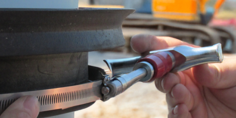
The external take-up clamps shall be constructed of Series 300 non-magnetic stainless steel and shall utilize no welds in their construction. The clamps shall be installed by torquing the adjusting screw using a torque-setting wrench available from the connector manufacturer.
Selection of the proper size waterstop for the structure and pipe requirements shall be in strict conformance with the recommendations of the connector manufacturer. Testing of completed field joints, if required, shall be conducted in strict conformance with the requirements of the connector manufacturer.
The installed waterstop, pipe, and structure shall conform with the requirements of ASTM D 2321 paragraph 7.10 for Manole Connections.